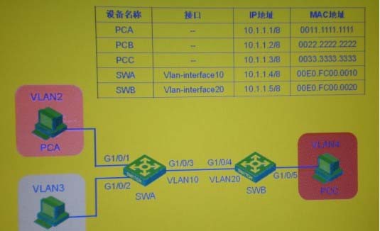
In the switching network shown in the figure, VLAN10 is set as Isolate-user-vlan on the switch SWA, VLAN2 and VLAN3 are set as the Secondary VLAN of VLAN 10; VLAN2? VLAN20 is created on the switch SWB, and VLAN20 is set as Isolate-user-vlan , VLAN4 is VLAN20 Secondary VLA after setting the IP address of each device as shown in the figure, the local proxy ARP function is enabled on both SWA and SWB. At first, the switch and pc did not learn their corresponding ARP entries in PCA. During the process of pinging PCB, PCA will send an ARP request. The source MAC address of the ARP request packet forwarded by the switch to PCB is
A. 0000.0000.0000
B. 0011.1111.1111
C. 00E0.FC00.0010
D. 00E0.FC00.0020
Answer: D
Latest GB0-371-ENU Dumps Valid Version with 341 Q&As
Latest And Valid Q&A | Instant Download | Once Fail, Full Refund
