In the switching network as shown in the figure, set VLAN10 to Isolate-user-vlan VLAN2 and VLAN3 to the Secondary VLAN of VLAN 10 on the switch SWA; create VLAN2? VLAN20 on the switch SWB, and set VLAN20 to Isolate-user-vlan, The Secondary VLA with VLAN4 being VLAN20 can be judged after setting the IP address of each device as shown in the figure
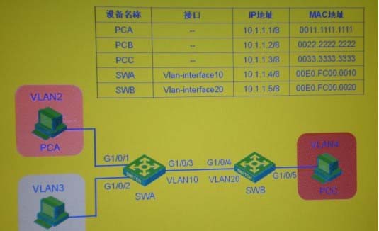
A . PCA can communicate with PCB
B . PCA can communicate with PCC
C . PCA can communicate with SWA
D . PCA can communicate with SWB
E . SWA can communicate with SWB
Answer: BDE
Latest GB0-371-ENU Dumps Valid Version with 341 Q&As
Latest And Valid Q&A | Instant Download | Once Fail, Full Refund
