In the switching network as shown in the figure, VLAN10 is set as Isolate-user-vlan on the switch SWA, VLAN2 and VLAN3 are the Secondary VLAN of VLAN 10; VLAN2? VLAN20 is created on the switch SWB, and VLAN20 is set as Isolate-user-vlan , VLAN4 is the Secondary VLAN of VLAN20. After setting the IP address of each device, check the MAC address table on SWA, it will show that the PCB belongs to (choose one or more)
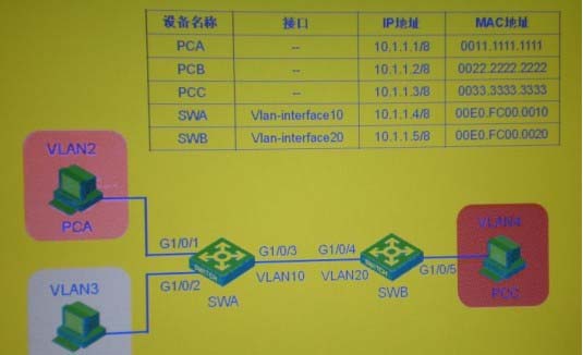
A . VLAN 1
B . VLAN2
C . VLAN3
D . VLAN4
E . VLAN 10
F . VLAN20
Answer: CE
Latest GB0-371-ENU Dumps Valid Version with 341 Q&As
Latest And Valid Q&A | Instant Download | Once Fail, Full Refund
