In the switching network as shown in the figure, VLAN10 is set as Isolate-user-vlan on the switch SWA, VLAN2 and VLAN3 are set as the Secondary VLAN of VLAN 10; VLAN2? VLAN20 is created on the switch SWB, and VLAN20 is set as Isolate-user-vlan , VLAN4 is VLAN20 Secondary VLA after setting the IP address of each device as shown in the figure, if the local ARP proxy function is enabled on both SWA and SWB, and both SWA and SWB are allowed to send ICMP packets, then on PCA Run the tracert 10.1.1.2 command, the PCA shows that the destination IP address reached by the first hop is
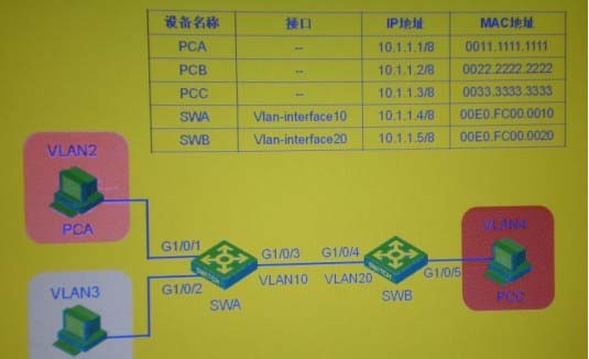
Answer: 10.1.1.5
Latest GB0-371-ENU Dumps Valid Version with 341 Q&As
Latest And Valid Q&A | Instant Download | Once Fail, Full Refund
