In the switching network as shown in the figure, VLAN10 is set as Isolate-user-vlan on switch SWA, VLAN2 and VLAN3 are set as Secondary VLAN of VLAN 10; VLAN2-VLAN20 is created on switch SWB, and VLAN20 is set as Isolate-user-vlan , VLAN4 is the Secondary VLAN of VLAN20. After setting the IP address of each device as shown in the figure, the following statement is correct (choose one or more)
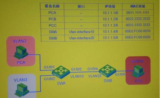
A . The packet of PCA enters from the GigabitEther1/0/1 port of SWA, and does not carry the VLAN tag after exiting from the GigabitEther1/0/3 port
B . The PCA packet comes out of the GigabitEthem1/0/3 port of SWA and enters the GigabitEthe1/0/3 port of SWB, and the VLAN Tag carried is VLAN2
C . When SWB accesses PCA, the VLAN tag carried by GigabitEthem1/0/4 of SWB is VLAN 1
D . SWB packets enter from SWA’s GigabitEthem1/0/3 port, and after exiting from GigabitEthem1/0/1 port, the VLANTag carried is VLAN2
Answer: A
Latest GB0-371-ENU Dumps Valid Version with 341 Q&As
Latest And Valid Q&A | Instant Download | Once Fail, Full Refund
