In the switching network as shown in the figure, VLAN10 is set as Super VLAN on the switch SWA, VLAN2 and VLAN3 are Sub VLANs of VLAN10, port Ethernet1/0/3 is Trunk port, PVID is VLAN1, allowing all VLANs to pass through; Create VLAN2~VLAN20 on SWB, port Ethernet1/0/4 as Trunk port, PVID is VLAN1, allowing all VLANs to be judged by setting the IP address of each device as shown in the figure (choose one or more)
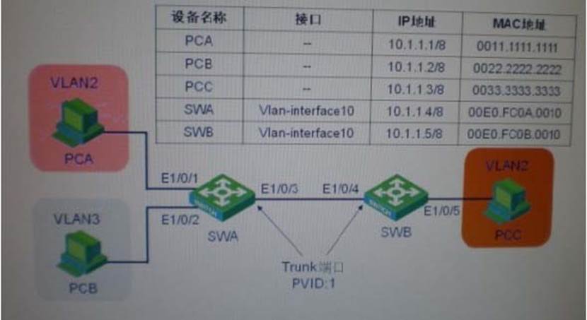
A . SWB can communicate with PCA
B . SWB can communicate with PCB
C . SWB can communicate with PCC
D . SWB can communicate with SWA
E . None of the above answers
Answer: E
Latest GB0-371-ENU Dumps Valid Version with 341 Q&As
Latest And Valid Q&A | Instant Download | Once Fail, Full Refund
