In the network connection shown in the figure, SWA and SWB are Layer 3 switches, running STP+VRRP, and after the initial configuration is completed, SWA is the root of STP and Master of VRRP, and SWC is the Layer 2 switch connected to the access terminal , The following description about network link failure is correct
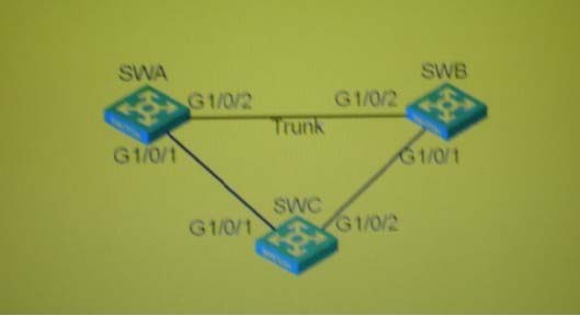
A . When the link between SWA and SWB is interrupted, the topology of STP will change, and both upstream ports of SWC will become Forwarding
B . When the link between SWA and SWB is interrupted, the VRRP Master will switch, and SWB will become the new VRRP Master
C . When the link between SWA and SWC is interrupted, the topology of STP will change, and G1/0/2 of SWC will become Forwarding
D . After the link between SWA and SWC is interrupted, the VRRP Master will remain unchanged, but the SWC downstream terminal will not communicate with the gateway.
Answer: A
Latest GB0-371-ENU Dumps Valid Version with 341 Q&As
Latest And Valid Q&A | Instant Download | Once Fail, Full Refund
